Images
Copyright Notice
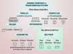
[fig i]: Drawing Viewpoints, or Transformation Systems
[fig ii]: Sketched plan and elevation
[fig iii]: Plan and elevations
[fig iv]: Plan, elevations and section
[fig v]: Perspective view of same building
[fig vi]: Subway map schematic
[fig vii]: Schematic section
[fig viii]: Elevation and section
[fig ix]: Sketch showing plan, elevation and parallel projections
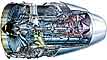
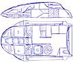
[fig x]: Detailed cutaway view
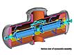
[fig xi]: Orthographic section view

[fig xii]: da Vinci cutaway skull
[fig xiii]: Exploded view

[fig xiv]: Combinations of oblique views in Indian art
[fig xv]: Isometric projection in Japanese art
[fig xvi]: Mixture of parallel projections
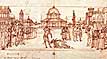
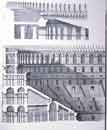
[fig xvii]: Renaissance perspective drawing
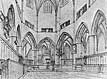
[fig iixx]: Renaissance perspective drawing
[fig ixx]: Oblique view with a scale applied
Introduction
Whether drawing from life or composing from the imagination for an illustration or visualization one will be making decisions concerning how to utilise the depth cues that we discussed last week. When one is more experienced, much of this process happens at the intuitive level.
One decision that requires more attention at the outset of a drawing is the selection of a viewpoint. Betty Edwards describes the process of using a picture plane/viewfinder on pages 98-101 and this leads to her discussion of sighting and informal perspective on pages 136-165 (this is your tutorial reading for this week). Her advice is quite sufficient in the context of the early stages of learning to draw what you see. However, the selection of viewpoint for applied graphic requirements including cartooning is more fundamentally related to the purpose for which the picture is to be produced and to the context in which it will be required to communicate, as we have seen in Lecture 2, Table 1.
Consider each of the following modes of spatial representation. Each is a method of portraying space and depth and using a particular viewpoint to highlight aspects of spatial relationships. The decision about which to use is related to a communicational objective. A creative designer or visualiser may even combine these modes and indeed other classes of information to achieve a unique objective. Indeed, Picasso and artists of the cubist movement proved that multiple viewpoints can be incorporated into a single image and spatial relationships juxtaposed.
- As listed here, the common modes of spatial representation are divided into two sub-categories according to whether the objective is to flatten the representation of three-dimensional spatial relationships, translating them into a two-dimensional reading; or whether the objective is to maintain an accurate mapping of the proportional relationships; or the illusion of three-dimensional depth:
- Two-dimensional views
- plans (also map, top view, bird’s eye view, aerial view)
- schematic views
- orthographic views
- cross-sections,
- cutaways and exploded views
- Three-dimensional views
- parallel projections, or paraline views
- oblique projections
- isometric projections
- linear perspective
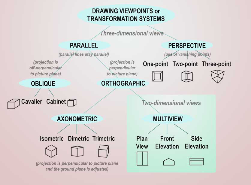
Chart depicting an overview of these viewpoints.
Two-dimensional views
Plans
A plan view (also called a map, a top view, a bird’s eye view, or an aerial view) is established so as to signify on a horizontal plane significant forms and spatial relationships. With the most basic plan volumetric forms are expressed in terms of area, however, variations that include other views of objects superimposed on a plan view are also common. Maps are possibly the commonest form of plan. When one thinks of a map one can understand how readily additional information can be incorporated into a simple plan view for example: orientation information, scales and other numerical data, names and symbols, notations of direction and movements. Using varying line weights, colour, tone and texture, boundaries can be illustrated, areas designated and interactions highlighted. It follows then that concepts involving function and other terms of reference can be readily incorporated into plans.
Related to plan views but different in that they may define, on a horizontal plane, relationships that are not necessarily or fundamentally about spatial information is a category called the schematic view. An example of a schematic view is a subway map where the rail lines indicated are not usually intended to represent actual distances or absolute directions but rather how the transport network is interconnected.
Orthographic views
A plan may also be considered as one of the three basic types of orthographic views: the plan, the elevation and the section. The plan is a two-dimensional horizontally mapped view of an object looking down, or indeed, its ‘footprint’. The elevation is similar to a plan except that it is a view from an axis perpendicular to the plan view, in other words, the picture plane is vertical. The section is a slice through the middle of the object in either the vertical or horizontal or an intermediary aspect.
Orthographic views are not necessarily equivalent to the three-dimensional optical view of an object, although sometimes an elevation may seem like a good representation of view from directly side on. But because depth clues are not usually incorporated into an orthographic projection it is easy for ambiguities to occur.
The main advantage of orthographic views is that they can be drawn to scale and so actual proportions and true shapes can be represented. Thus they are commonly used for house plans and engineering designs. To portray a meaningful conceptualization of a three-dimensional object, two elevations from axes at right angles to each other and a plan view are usually presented for cross-referencing.
Cross-sections, cutaways and exploded views
As mentioned above, a simple section is a kind of orthographic view. They are most often used to show materials of construction and the physical and spatial constituents of internal spaces. Thicknesses of interior structures not possible to show in an elevation may be shown.
Cross-sectioning is a very useful device for illustrators. The technique of showing cutaway views can be incorporated with two and three-dimensional modes of representation. Cutaways are useful for showing both exterior form and interior workings in the same illustrations and can readily show how things fit together. A complicated section view could also include exploded view elements to enhance the communication of this type of information. Sections are often used to show biological information.
Three-dimensional views:
Whereas two-dimensional views are concerned with expressing two axes of dimension at any one time, and so are essentially abstractions or mappings of spatial relationships, three-dimensional views are intended to portray the three axes—width, height and depth—at a glance and thus tend to correspond more to depth and spatiality as we perceive and understand it in the visual sense and motile sense (to do with moving through the world).
Parallel projections or paraline views
With parallel projections the depth of an object is projected in space on the basis that parallel lines remain parallel (See fig i). The ground plane appears tilted up in accordance with the angle of view. If an imaginary square grid were imposed on the ground plane the receding lines of the grid would not appear to converge. Because edges and planes in the x, y and z dimensions remain parallel an object represented in paraline view maintains its proportional integrity when scaled. Paraline views are relatively easy to draw and are useful for drawing smaller scale objects that would not be expected to show a high degree of convergence.
Oblique views
These are a class of parallel projection with one or both of the following features:
the orientation of the object is rotated so that, if it were a cube it would be aligned at an angle oblique to:
- the picture plane of 30, 45 or 60 degrees (plan oblique);
- the elevation of the apparent ground plane is at an oblique angle of 30, 45 or 60 degrees (elevation oblique).
When an oblique view of a cube is formally constructed the side receding at an oblique angle is made the same length as the side that is parallel to the picture plane. Because we make a perceptual adjustment for the oblique side receding into depth, a cube drawn this way always looks as if the receding side is too long (see 'cavalier' oblique in fig i). So to counteract this effect the receding side is often shortened. When it is this looks normal to us. An oblique drawing with this adjustment made is called a 'cabinet' oblique.
Isometric views
The outline shape of a cube drawn in isometric view is actually a regular hexagon (see fig i). This is because in an isometric drawing the x, y and z axes are equidistant and all equally sized edges of faces are represented as such. Because no one plane is emphasised a cube drawn this way may appear ambiguous. Yet the distorted appearances that arise from oblique views are not apparent with isometric drawing.
Perspective views
Perspective views are particularly successful for portraying spatial representations of geometry and so of course are most suitable for architectural interiors and exteriors and cityscapes. There are different perspective systems but the most commonly used one in contemporary times is known as linear perspective. Generally speaking, it is agreed that perspective matches how we perceive spatiality and depth.
The linear perspective system is commonly categorized into three sub systems: one point, two point, and three point perspective (see fig i). They are in fact all interrelated. One may use all in the same drawing. Which sub system one uses simply depends on where the object is relative to the view point.
The first reading for this week is a section from the highly recommended text for this unit by Francis Ching, Drawing, a creative process. In the reading provided via the Course Resources Online (CRO) section of the CQU Library, pages 108-127, Ching illustrates types of linear perspective, indicates how they are constructed and, typical uses.
Conclusion
So far this talk about different types of views may seem orderly and systematized, but the classification of different types of drawing systems is actually far from being an exacting and regular solution to all viewing problems. This is particularly so with perspective systems. Betty Edwards is wise to recommend informal, observed perspective, and to advise that the mathematical and philosophical arguments over perspective systems can get in the way of simply drawing. As eminent art historian Erwin Panofsky put it in his essay originally published in 1927, Perspective as Symbolic Form,
Perspective subjects the artistic phenomenon to stable and even mathematically exact rules, but on the other hand, makes that phenomenon contingent upon human beings, indeed upon the individual: for these rules refer to the psychological and physical conditions of the visual impression, and the way they take effect is determined by the freely chosen position of a subjective “point of view.”
(Panofsky, 1991, p67)
The renowned piece of scholarship from where the above paragraph was cited is remarkable in that the historical notes and references are longer than the essay itself! In the essay Panofsky convincingly argues the fairly radical position that, it is questionable why we should consider linear perspective to be the most realistic form of drawing with which to represent the world, because perspective is simply one among many human symbolic systems. A second reading provided in association with this week’s lecture is a chapter from a critical introduction to new media by Martin Lister and others. Talking about immersive virtual reality (VR) as a component of our experience of new media, the authors note how the "character of perspectival representation" is embodied in modern technological media. They extrapolate Panofsky's argument to suggest that we might think of perspective not only as a means of expression and a way of "adding meaning to what is represented" but also as a "technology for constructing the space in an image". (Lister et. al. 2003: 129)
By way of postscript to this topic, for students who have not been exposed to Cubist art, it would be worth looking at the related links about that movement. Cubism was a reaction against pictorial realism that lead its proponents to experiment with mutiple viewpoints in painting.
Next week the first part of the lecture is based around another essay by Panofsky where he talks about systems of representing human proportions as reflections of worldview, which is an extension of his ideas on perspective.
References
Ching, F. D. K., 1990, Drawing, A creative process, John Wiley & Sons, pp: 108-112
Lister, M, et.al. 2003, New Media: a critical introduction, Routledge London, New York, pp: 125-136
Panofsky, E, 1991, Perspective as Symbolic Form, Woods, C. S., (tr), Zone Books, pp: 27-45 including notes 1-29 on pp: 73-112.